
Which Composite Material Forming Process Can Provide the Strictest Dimension Tolerance for Non-Standard Carbon Fiber Geometries?
 By Qi Bing, CEO & Technical Director, Hongjin Composite Materials Co., Ltd. | Updated August 2026 | 19 min read
| QUICK ANSWER
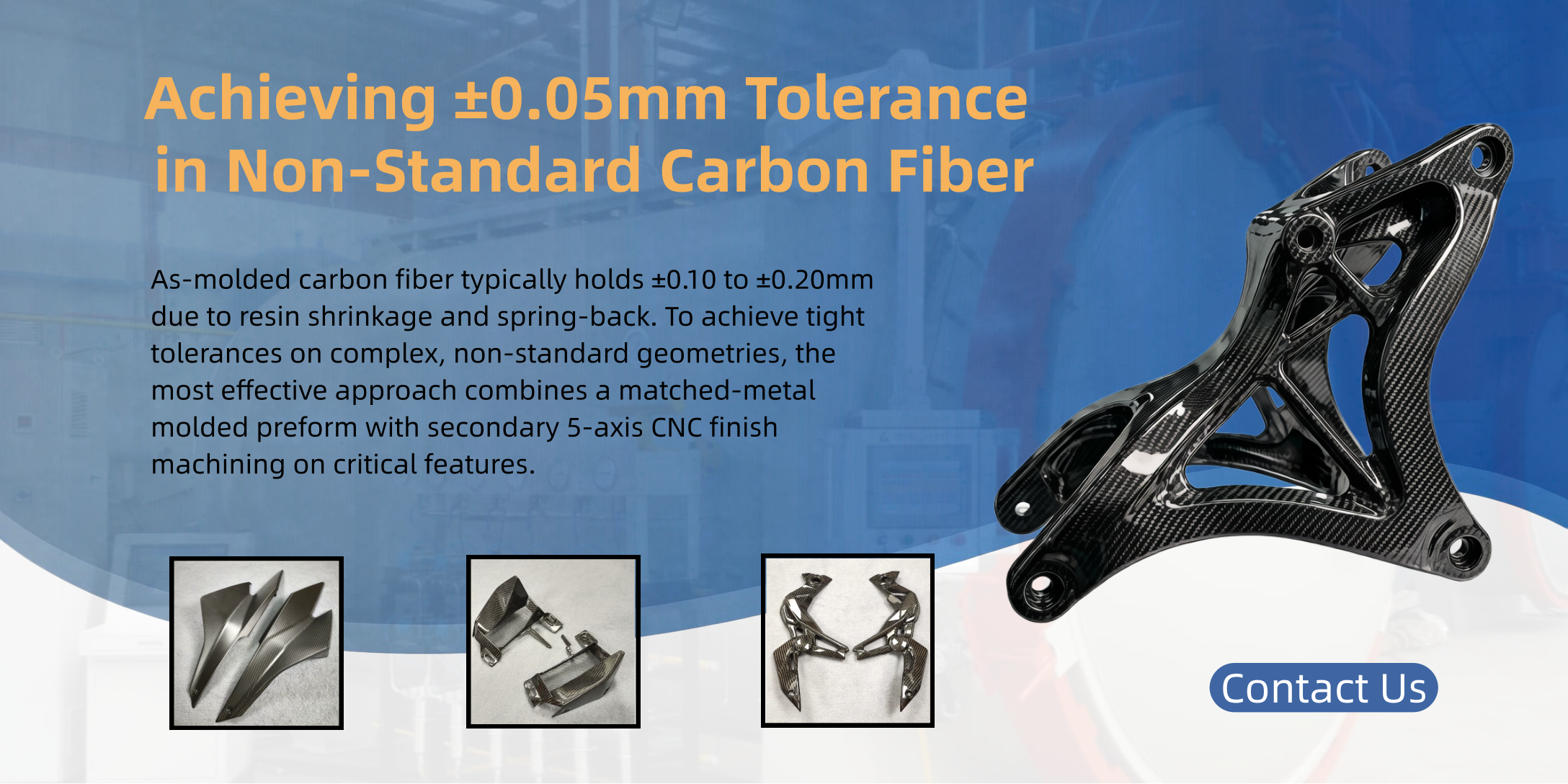
For non-standard, geometrically complex carbon fiber parts, no single forming process holds tight tolerance on its own — the shape comes from a molding stage and the precision comes from a secondary machining stage. In my shop, the combination that consistently gets us to ±0.05 mm or tighter on critical features is a matched-metal or closed-mold preform (compression molding, HP-RTM, or autoclave prepreg over a CNC-machined steel/aluminum tool) followed by 5-axis CNC finish machining of mounting faces, bore diameters, and mating edges. As-molded tolerance alone, even in a good aluminum tool, typically runs ±0.10–±0.20 mm because of resin shrinkage, spring-back, and fiber-bed variation — machining is what removes that variability where it actually matters to your assembly. |
I get some version of this question almost every week from a buyer who has a part that doesn’t look like anything in a catalog — a bracket with three non-parallel bolt faces, a housing with an off-axis bore, a hydrofoil section that tapers in two planes at once. They’ve usually already been told by one supplier that “carbon fiber can’t hold tight tolerance” and by another that “we can match anything, no problem.” Neither answer is honest on its own, and after ten years of quoting exactly these parts, I’d rather give you the real mechanics of where tolerance comes from in a composite part, so you can ask your supplier better questions than “what tolerance can you hit.”
The short version: tolerance in carbon fiber isn’t a property of the material or even of a single “process.” It’s the sum of three separate error sources — the tool, the cure, and the finishing step — and non-standard geometry makes all three worse at the same time. Let’s walk through it in the order I actually think about it on the shop floor.
1. Why Non-Standard Geometry Breaks “Standard” Tolerance Numbers
Every process datasheet you’ll find online quotes a tolerance range for flat or gently curved panels, because that’s the easy case to test and publish. A non-standard part — asymmetric ribs, compound curvature, thick-to-thin transitions, blind bosses — introduces three things that flat-panel numbers don’t account for:
- Differential shrinkage: thick sections and resin-rich pockets cool and cure at different rates than thin walls, so the part pulls itself slightly out of shape as it comes off the tool.
- Spring-back on curved and angled faces: laminate wants to relax toward its free-form curvature once tool pressure is released, and the effect is larger the more the geometry deviates from a simple flat or cylindrical shape.
- Fiber bridging and wash in tight radii: in corners under about 3–4 mm internal radius, fiber tow doesn’t conform perfectly to the tool surface, which shows up as local dimensional and thickness variation exactly where fasteners or mating parts usually sit.
None of this means non-standard parts can’t be held to tight tolerance — it means the tolerance has to be designed into the process plan, not assumed from a generic spec sheet.
2. Fiber Grade Also Changes What Tolerance You Can Realistically Hold
This part gets skipped in almost every article I’ve read on this topic, and it bugs me, because fiber grade affects tolerance almost as much as process choice does. A stiffer fiber resists spring-back better once it’s out of the tool — it simply has less tendency to relax toward its own preferred shape. A cheaper, lower-modulus fiber will hold a flat panel fine, but put it on a non-standard part with a tight radius and an off-axis flange, and you’ll see more dimensional drift than the resin or the tool ever gets blamed for.
| Fiber Grade | Tensile Strength (MPa) | Tensile Modulus (GPa) | Elongation at Break | Relative Cost | Typical Fit for Tight-Tolerance Parts |
| T300 | 3,530 | 230 | 1.5% | Baseline | Adequate for flat/simple geometry only |
| T700S | 4,900 | 230 | 2.1% | 1.1–1.3x T300 | Good all-round choice, our default for structural brackets |
| T800H | 5,490 | 294 | 1.9% | 1.6–2.0x T300 | Preferred for thin-wall, tight-radius non-standard shapes |
| T1000G | 6,370 | 294 | 2.2% | 2.3–2.8x T300 | Aerospace-grade, used when spring-back must be minimized |
| M40J (high-modulus) | 4,400 | 377 | 1.2% | 2.5–3.0x T300 | Best dimensional stability, lower impact tolerance |
Table 3: Common PAN-based carbon fiber grades and how their mechanical properties translate to dimensional stability on complex geometry. Cost figures are relative industry ranges, not our fixed pricing.
My honest opinion, and I know some engineers will push back on this: for most non-standard industrial and marine brackets, T700S is the sensible default. T800H and above earn their premium on thin, aerodynamic, or aerospace-adjacent shapes where every tenth of a millimeter of spring-back actually matters to the customer. Paying for T1000G on a pump housing bracket is, in my view, money spent on a spec sheet number rather than on the tolerance the customer actually needs — I’ve had this exact argument with a buyer’s procurement team more than once.
3. Resin System Matters More Than People Assume
If fiber grade is under-discussed, resin system is almost never discussed at all outside of a materials lab. But shrinkage during cure, and how the resin behaves as it cools from cure temperature to room temperature, is one of the biggest hidden contributors to out-of-tolerance parts on non-standard geometry.
| Resin System | Cure Shrinkage | Typical Cure Temp | Glass Transition (Tg) | Dimensional Stability Rating | Notes |
| Standard epoxy (120°C cure) | 1.5–2.0% | 120–135°C | 120–130°C | Good | Our default for most OEM parts |
| High-temp epoxy (180°C cure) | 1.0–1.5% | 175–180°C | 170–190°C | Very good | Used for under-hood automotive, engine-adjacent parts |
| Vinyl ester | 3.0–6.0% | 80–120°C | 90–110°C | Fair | Cheaper, but shrinkage makes tight tolerance harder |
| Bismaleimide (BMI) | 0.8–1.2% | 190–230°C | 230–290°C | Excellent | Aerospace-grade, high cost, best dimensional retention |
| Phenolic | 6.0–8.0% | 150–170°C | 150–200°C | Poor for tight tolerance | Chosen for fire rating, not dimensional precision |
Table 4: Resin systems ranked by cure shrinkage and dimensional stability. Vinyl ester and phenolic are common in marine and fire-rated applications but need extra tolerance allowance or secondary machining.
Here’s a mistake I still see buyers make: they spec vinyl ester because it’s cheaper per kilo, then they’re surprised when a non-standard part with a tight bore comes in out of spec. Vinyl ester isn’t a bad resin — we use it plenty in marine work where cost and corrosion resistance matter more than a couple tenths of a millimeter — but if the part has a tight-tolerance feature, I’ll tell a customer upfront that we either move to epoxy or we plan on machining that feature afterward. Trying to mold vinyl ester directly to a bearing-fit tolerance is, frankly, a losing bet.
4. Tolerance Benchmarks by Forming and Finishing Process
Here are the ranges I actually quote against, based on production data from our own tooling and cross-checked against published composite manufacturing references. These are for carbon fiber/epoxy laminates in the 2–6 mm wall range; thinner or thicker sections shift the numbers.
| Process | As-Formed Tolerance | Best Use for Non-Standard Geometry | Typical Cycle |
| Wet layup / open mold | ±0.3–0.5 mm | Low-volume prototypes, large low-load shells | Hours (hand cure) |
| Prepreg / autoclave, matched tool | ±0.1–0.2 mm | Aerospace-grade structural shapes, thin-wall complex curvature | 2–6 hrs cure |
| Compression molding, steel tool | ±0.1–0.15 mm | Medium–high volume, ribbed or stepped geometry | 3–10 min/part |
| HP-RTM / closed-mold injection | ±0.08–0.15 mm | Class-A surfaces, enclosed cavities, bosses | 3–8 min/part |
| Filament winding | ±0.15–0.3 mm (OD) | Axisymmetric tubes, shafts, pressure vessels only | Continuous |
| CNC waterjet trim (secondary) | ±0.10 mm | Outer profile trimming, no depth features | Seconds–minutes |
| CNC milling, 3–5 axis (secondary) | ±0.02–0.05 mm | Bolt holes, mating faces, bosses, critical fits | Minutes/part |
Table 1: Achievable dimensional tolerance by process stage, based on our production records and cross-referenced against published CFRP machining data.
Notice the pattern: no molding process alone reaches the tolerance that precision CNC machining reaches on its own. That’s not a flaw in molding — it’s just what curing a fiber-resin system under heat and pressure will and won’t do. The tightest overall result always comes from pairing a dimensionally stable molded preform with machined critical features.
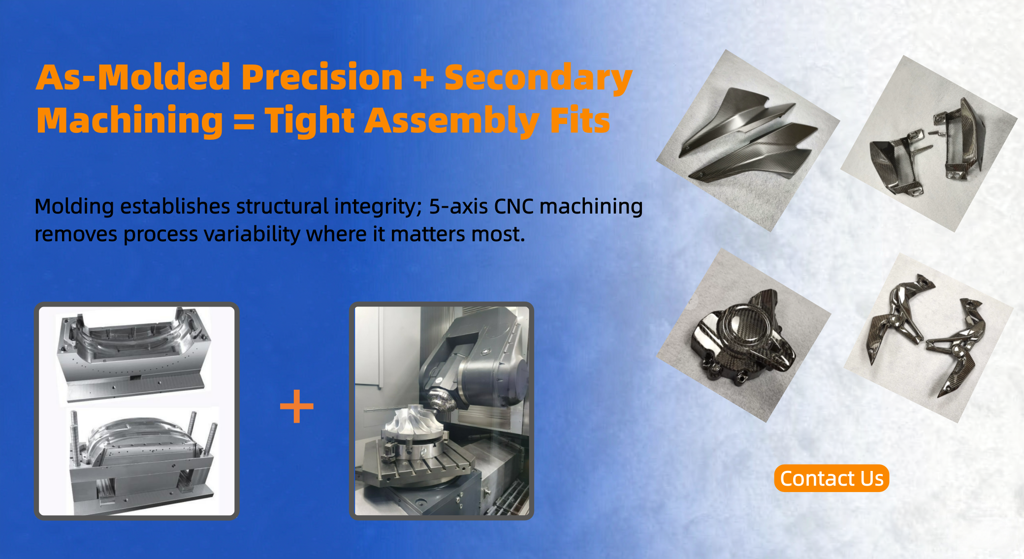
5. The Combination That Actually Wins: Molded Preform + 5-Axis Finish Machining
When a customer needs ±0.05 mm or tighter on specific features — a bearing bore, a flange face that has to seal, a bracket that bolts to a metal chassis — we don’t try to mold that tolerance directly. We mold the part slightly oversized on those features and machine them to final dimension afterward. This is standard practice in aerospace composite manufacturing, and it works just as well for industrial and marine parts once a shop has the fixturing to hold a cured composite part without crushing it.
5.1 Step 1 — Build a Dimensionally Stable Preform
For non-standard geometry, we default to a CNC-machined aluminum or steel tool (steel above roughly 500 shots for wear resistance) and either compression molding or HP-RTM for the bulk shape. Autoclave prepreg comes in when the part is thin-walled with tight curvature and load-bearing skins, where fiber placement control matters more than cycle time. The tool itself needs to be held to roughly one-third of the part’s final tolerance requirement — if the part needs ±0.1 mm, the cavity needs to be machined and inspected to about ±0.03 mm, because the laminate will never be more accurate than the surface it was formed against.
5.2 Step 2 — Control the Cure, Not Just the Shape
A lot of dimensional drift traces back to uneven cure temperature across a non-standard part — thick ribs lag behind thin skins, and that lag shows up as warp after demold. We instrument new tools with multiple thermocouples during process validation specifically to catch this before it becomes a customer-facing problem, and we adjust cure ramp rates section by section rather than using one blanket cycle for the whole tool.
5.3 Step 3 — Machine the Features That Actually Need Tolerance
Once the part is stable, a 5-axis CNC center with diamond-coated or PCD tooling finishes bores, bolt faces, and mating edges to ±0.02–0.05 mm, using the molded surface only as a rough locating datum. This is also where we cut features that would be difficult or impossible to mold directly — undercuts, cross-drilled holes, or a bolt pattern that has to align with an existing metal assembly the customer already owns.
6. A Quick Word on Tool Material — Because It Gets Overlooked Too
I said above that the cavity needs to be machined to about a third of the part’s final tolerance. What I didn’t say is that the tool material you pick decides how long that accuracy actually lasts in production, which matters if you’re running thousands of parts rather than dozens.
| Tool Material | Typical Tool Life (Shots) | Relative Tooling Cost | Dimensional Stability Over Life | Best Fit |
| Aluminum (6061/7075) | 500–2,000 | Low | Good early, wears faster on abrasive fiber | Prototypes, short-run production |
| P20 tool steel | 5,000–20,000 | Medium | Very good, minimal wear drift | Medium-volume OEM parts, our usual choice |
| H13 hardened steel | 20,000+ | High | Excellent, industry benchmark | High-volume automotive/industrial programs |
| Composite (epoxy) tooling | 50–300 | Low | Fair, sensitive to thermal cycling | Very low volume, large low-load shells |
Table 5: Tool material trade-offs for compression molding and HP-RTM cavities used on non-standard carbon fiber geometry.
If a customer tells me they need 50 prototype parts, I’m not going to sell them an H13 tool — that’s just poor advice dressed up as “future-proofing.” But I’ve also seen shops undersell a P20 tool to a customer who’s about to scale into automotive volumes, and then the customer is back six months later paying for a second tool build because the aluminum cavity walked out of tolerance at shot 800. Match the tool to the actual production forecast, not to whichever option is easiest to quote quickly.
7. Where I Push Back on Common Industry Advice
A few things get repeated so often in this industry that people stop questioning them. I don’t always agree, so I’ll say where and why.
- “Autoclave prepreg is always the tightest-tolerance option.” Not for non-standard geometry with bosses or ribs — vacuum bag pressure alone doesn’t consolidate those features as consistently as a matched-metal tool under full compression pressure. Autoclave wins on thin, curved skins; it doesn’t automatically win everywhere.
- “Higher fiber grade always means a better part.” Only if the failure mode you’re worried about is spring-back or stiffness-limited. For impact-prone applications, a lower-modulus, higher-elongation fiber can outperform a premium high-modulus one, tolerance numbers aside.
- “If a supplier can’t quote a tolerance instantly, they don’t know what they’re doing.” I’d argue the opposite — on genuinely new, non-standard geometry, a supplier who wants a tool trial before committing to a number is being honest with you, not stalling.
8. Standards We Machine and Inspect Against
Because composite-specific dimensional standards are thinner than the metalworking world’s, we lean on a mix of general tolerancing and composite testing standards to keep quotes and inspection reports consistent across customers and regions.
| Standard | Scope | How We Use It |
| ISO 2768-1/2 | General tolerances for linear and angular dimensions | Baseline for as-molded features without individual GD&T call-outs |
| ASME Y14.5 | Geometric dimensioning and tolerancing (GD&T) | Applied to machined datums, bores, and flatness on critical faces |
| ASTM D695 / ISO 604 | Compressive properties of rigid plastics/composites | Validates that machined thin sections still meet strength targets |
| ASTM D3039 / ISO 527 | Tensile properties of polymer matrix composites | Coupon testing on new tool qualification runs |
| ASTM D7136 | Damage resistance (drop-weight impact) | For parts where machining is near an edge or cutout |
Table 2: Reference standards applied during tool qualification and first-article inspection at our facility.
9. A Recent Project: Off-Axis Pump Housing for a Marine Client
A European marine equipment customer came to us with a small carbon fiber pump housing that had two non-parallel mounting faces, a stepped internal bore for a bearing press-fit, and a wall thickness that varied from 2.5 mm to 6 mm across the part — exactly the kind of geometry that breaks generic tolerance promises. Their incumbent supplier had been molding it as-is and seeing roughly 20% of parts fail bearing press-fit inspection.
We rebuilt the tool in P20 steel with the bearing bore and both mounting faces deliberately oversized by 0.3 mm, molded the housing by compression molding at a controlled, ramped cure profile to manage the thick-to-thin transition, and finished the bore and both faces on a 5-axis mill using the outer shell as a rough datum. Final bore tolerance came in at ±0.03 mm and flatness on the mounting faces held to 0.04 mm across the part, with zero press-fit failures across the qualification batch. Piece price rose about 12% over the pure-molding approach, but scrap and rework on the customer’s assembly line dropped to essentially zero — which is the number that mattered to them.
10. How to Specify Tolerance So Your Supplier Can Actually Hit It
Most tolerance disputes I’ve seen over the years come from the drawing, not the process. A few habits make quoting and delivery much more reliable on both sides:
- Call out GD&T only on features that need it — bores, mating faces, bolt patterns — and leave everything else to a general tolerance block. Tightening every dimension on the drawing just raises cost without improving fit.
- Tell your supplier which faces are functional datums versus cosmetic surfaces, so machining time gets spent where it changes assembly outcomes.
- Ask for a first-article inspection report with a CMM point cloud on new non-standard geometry, not just a certificate of conformance — it catches tool-wear drift early, long before it becomes a shipment full of out-of-spec parts.
- If the part mates to metal, share the metal part’s actual measured dimensions, not just its nominal drawing values — composite tolerance only matters relative to what it’s bolting to.
11. Frequently Asked Questions
11.1 Can compression molding alone hold ±0.05 mm on a complex part?
Rarely, and I wouldn’t quote it that way. Compression molding in a well-built steel tool typically holds ±0.10–0.15 mm as-molded on non-standard geometry. To reach ±0.05 mm or tighter, we mold slightly oversized on the critical features and finish them with CNC machining.
11.2 Is autoclave prepreg always more precise than compression molding?
Not automatically — it depends on the geometry. Autoclave prepreg gives better control over fiber placement and thin-wall curvature, which matters for aerodynamic or hydrodynamic surfaces. For thicker, ribbed, or bossed geometry, a matched-metal compression tool often holds dimension just as well, at a fraction of the cycle time and cost.
11.3 Does tighter tolerance always mean higher cost?
Yes, but not proportionally across the whole part. The cost increase comes almost entirely from the specific features you tolerance tightly, not from the part as a whole — which is why separating functional datums from cosmetic surfaces on the drawing keeps the price reasonable.
11.4 What tolerance can you commit to on a new, non-standard geometry?
We won’t give a number before running a tool trial with CMM inspection, because spring-back and shrinkage behavior genuinely differ by geometry, wall thickness, and fiber schedule. What we can commit to upfront is the inspection method and the process route — molded preform plus machined critical features — and confirm the achievable number once first-article parts exist.
12. Where I’d Start If This Is Your Part
If you’re looking at a non-standard carbon fiber geometry and a drawing full of tight tolerances, the first conversation worth having with any supplier isn’t “what’s your tolerance capability” — it’s “which features on this part actually need to be tight, and how will you hold them.” Send us your drawing and tell us which faces mate to something else; we’ll come back with a process route, not just a quote.
13. About the Author
I’m Qi Bing, CEO and Technical Director at Hongjin Composite Materials. I’ve spent the last decade running production and process engineering for carbon fiber OEM parts across sporting goods, industrial machinery, medical devices, motorcycle and automotive components, marine hardware, and aerospace-adjacent brackets. Our team is a little over ten engineers, and between us we’ve built and qualified more compression, HP-RTM, and autoclave tools than I can count offhand. The numbers and opinions in this article come from our own tool trial data and production records, not a materials textbook — which is also why I’d rather tell you where a process falls short than pretend every option is perfect.
— Qi Bing, CEO & Technical Director, Hongjin Composite Materials Co., Ltd.


Leave a Reply
Want to join the discussion?Feel free to contribute!